Service explanation for JA-82K 1 Central controller architecture - The central controller has 50 addresses (01 to 50), 50 wireless items can be read in, e.g. detectors, control panels, remote controls, sirens ...- When triggering, the detector sends a unique signal. The central receiving the signal links the appropriate reaction...
JA-82K (part 1)
Too much choice? Chat or call us at 085-0160316
There are no products in these categories. Shop on.

Service explanation for JA-82K
1 Central controller architecture
- The central controller has 50 addresses (01 to 50), 50 wireless items can be read in, e.g. detectors, control panels, remote controls, sirens ...
- When triggering, the detector sends a unique signal. The central receiving the signal links the appropriate reaction to each signal. E.g. the reaction for a door contact can be an immediate or delayed alarm depending on the position of the DIP switch. A remote control transmits a signal for arming, disarming or panic.
o The control unit is pre-programmed so that each wireless element is linked to the appropriate response. These reactions can be modified later. See 12.39
- Wireless items can be linked to 3 sections: A,B or C. In partial arming, you can arm only A, or arm A+B, or arm A+B+C. In a "SPLIT" system, you can arm both A and B separately, when both are armed, automatically the common section C is also armed.
- The control unit has 2 wired inputs, these are automatically linked to addresses 01 and 02. When these inputs are not used, these addresses can be used for wireless items. Some wireless items also possess a wired input, such as control panels, magnetic contacts and PIR motion detectors.
- The control unit has 2 alarm outputs: IW = internal alert and EW = external alert. Both signals are also available as wireless signals.
- There are 2 programmable outputs in the control unit, PGX and PGY. The functions of the PGX and PGY can be configured. The PG outputs can be used not only as wired outputs, but also as radio signals to control the UC and AC receiver outputs.
The central unit has 50 addresses (01 to 50), 50 wireless items can be read in, e.g. detectors, control panels, remote controls, sirens ...
When triggered, the detector sends a unique signal. The control unit that receives the signal links the appropriate response to each signal. E.g. the reaction for a door contact can be an immediate or delayed alarm depending on the position of the DIP switch. A remote control transmits a signal for arming, disarming or panic. These reactions can be modified later. See 12.39
Wireless items can be linked to 3 sections: A,B or C. In partial arming, you can arm only A, or arm A+B, or arm A+B+C. In a "SPLIT" system you can arm both A and B separately, when both are armed, automatically the common section C is also armed.
The control unit has 2 wired inputs, these are automatically linked to addresses 01 and 02. When these inputs are not used, these addresses can be used for wireless items. Some wireless items also possess a wired input, such as control panels, magnetic contacts and PIR motion detectors.
The control unit has 2 alarm outputs: IW = internal alert and EW = external alert. Both signals are also available as wireless signals.
There are 2 programmable outputs in the central unit, PGX and PGY. The functions of the PGX and PGY can be configured. The PG outputs can be used not only as wired outputs but also as radio signals to control the UC and AC receiver outputs.
The system can be operated via user codes or access cards ( Type,Proximity EM technology). The system allows 50 different users. The system can also be operated by remote control, and if the control unit has the appropriate communicator, it can be operated via GSM or via the Internet.
It is possible to associate different responses with access codes or access cards, and if you use a "SPIT" system, it is possible to specify which code/card has access to section A or to section B. Each of the max. 50 users can have its own 4-number code and/or its own card. Arming and disarming is possible by both card and code, and when higher security is required, a combination card+code is also possible to arm/disarm.
Programming of the system is possible via the OASIS control panel JA-80F(wireless) and the JA-80E(wired), as well as via computer with the Comlink software. Further options offer programming via telephone/GSM or via the internet.
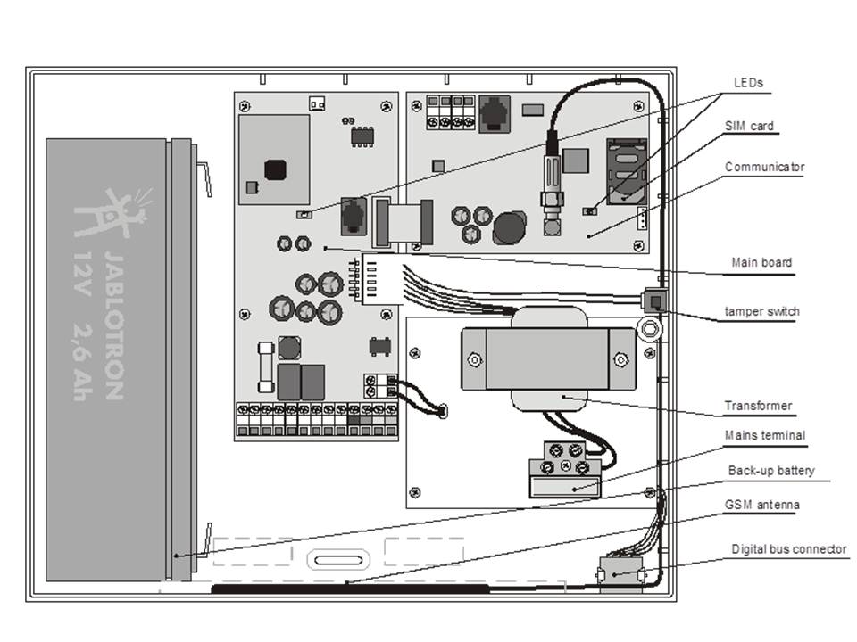
The control unit has a power supply module and there is room for a 12V 2.6Ah battery for Autonomy.
The control unit also has a digital bus equipped with connection terminals and RJ connectors. This digital bus can be used for the wired control panel or for connection to the PC via the USB interface.
The control unit can be equipped with an optional communicator for external communication to the system. The LAN/PSTN communicator JA-80V and the GSM communicator JA-80Y allow communication to the control room. The voters can send SMS messages and allow remote control of the system via telephone/GSM or via the internet. The JA-80X PSTN communicator can report alarms over the traditional telephone line via recorded messages.
NoteOASIS JA-82K has 3 modes, user mode, maintenance mode and installation mode. User mode is for daily use of the system by the authorised user.(e.g. arming/disarming). Maintenance mode is for the MASTER code holder (system administrator) for limited programming of the system (e.g. modification of codes/cards). Installation mode is only accessible to installers, and is used for programming and operating all aspects of the system.
1.1 Optional system configurations
In the European Union, according to the standard regulations, the OASIS central unit complies with grade 2 according to EN-501-xx.
For this purpose, the central controller should have minimum following configurations:
- At least 2 non "non-backup sirens" (JA-80L or SA-105) + dialer class ATS2 (JA-80Y, JA-80V or JA-80X)
- At least 1 "backup-battery" siren (JA-80A or OS-350) + dialer class ATS2 (JA-80Y, JA-80V or JA-80X)
- No siren + communicator class ATS3 (JA-80Y or JA-80V)
Note:The configurations recommended above are based on the EU standard EN-50131-1 in force at the time of drafting this manual
2 Installation of the central controller
The central unit can be fixed to the wall with 3 screws. The drilling diagram can be found on the last page of this manual
- As the central unit communicates via radio frequency, we recommend not installing it near large metal objects that may block radio communication.
2.1 Power cable wiring
The power cable of the power plant should be connected by competent persons with the appropriate electrical engineering degree. 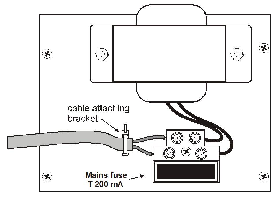
The power cable of the central unit is double shielded (safety class 2) and has no additional earthing.
- The double-shielded power cable should have a minimum section of 0.75 to 1.5mm². This cable should be connected to the switchable fuse of 10 AMPS of the central unit, this fuse is of type T200mA/250V
- Fix the cable in the cable holder of the central unit, make sure that the wire ends are well shielded and fix in the connector.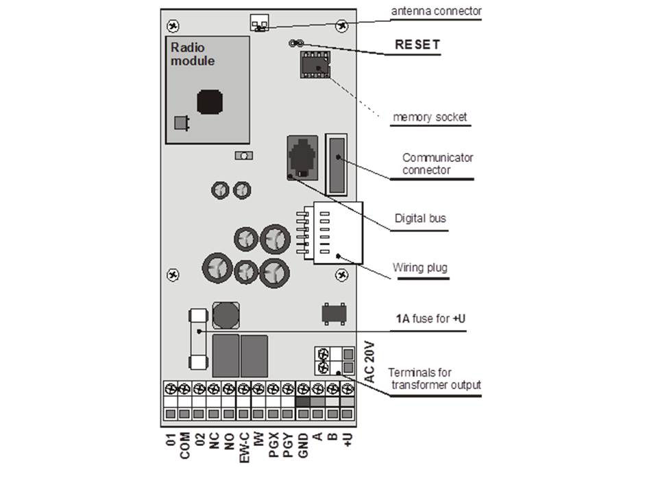
3 Central controller memory
The memory of the central unit is stored in the EPROM. If the central unit is damaged, it can be removed and inserted into a new central unit without losing the data. This way, all settings of read-in detectors, access codes and cards are preserved. The new control unit will thus be an exact copy of the previous control unit.
Note
- The communicator settings are not in this memory
- The memory should only be inserted/removed in a de-energised state.
- It is always recommended to save the memory on PC via the Comlock software. This way, the data is preserved even in case of very heavy damage.
4 Central: Connectors and terminals
Antenna connector - This is used to connect to the internal antenna or to external antennas such as the AN-80 or AN-81.
Reset link (normally open) - To reset the panel, one must short-circuit this link before powering up the panel. This link can also be used to read a central unit by briefly shorting it when the central unit is powered up.
Digital bus connector - For connecting the wired control panel JA-81 E or the PC for the Comlink software via the JA-80T USB interface cable. The same digital bus can be seen at the bottom right of the control unit housing. The same bus is available via terminals GND,A,B,+U
Communication connector - this is the connector for the optional communicator. (PSTN, LAN or GSM)
Internal wiring connector - Connects the internal wiring in the control panel housing.
Connect terminals:
AC 20V this is where you connect the transformer output.
01, GND, 02 are wired inputs of the control panel.
- The responses for these inputs to trigger are set by the settings of addresses 01 and 02. The factory setting for these 2 wired inputs are both delayed inputs in section C.
- Terminals 01 and 02 use resistors in loop
o Connect to GND via 1 to 5 kW = triggered input,
o Up to 5 normally closed magnet contacts can be placed in series and connected to 1 hard-wired input, each magnet contact should have 1 resistor in parallel of 1KW ( See diagram below)
o Multiple tamper contacts can be placed in series without additional resistor in parallel. The number of tamper contacts is not limited, and can be combined with trigger contacts with resistors in parallel of 1KW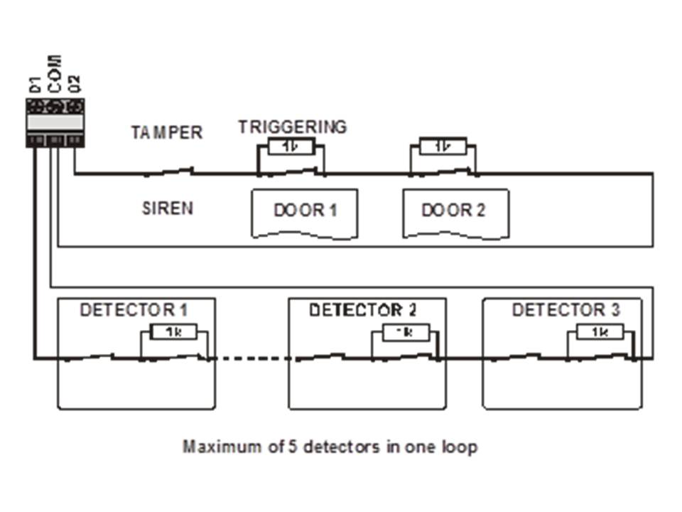
o If wireless items are registered at address 1 and address 2, the corresponding input will be deactivated.
o If you do not use the hard badrade input, nor do you read any wireless item at address 1 or 2, the input must be connected to GND via a 1KW Resistor.
NC - Normally closed contact for the external warning.
NO - Normally open contact for the external warning
EWC - common contact for the external warning relay. Maximum 1A/60V. The control unit also transmits the warning radio signal to the wireless sirens.
IW - Internal warning (siren) output. This output is connected to GND during an internal alarm. A standard internal siren can be connected to the +U and IW connectors (max 0.5A). The IW output status is also wirelessly transmitted to the wireless indoor siren.
The major difference between an internal and external alarm is during the walk-in delay. When an instant detector is triggered during the walk-in delay, only the indoor siren will be triggered, the outdoor siren will only go off after the walk-in delay.
PGX, PGY -are 2 programmable outputs. When an output is triggered it will switch to GND with a maximum load of 0.1A/12V. The factory setting of the PGX is the function on/off which you can control from the keypad via the keys *81 / *80 or with the arrow keys ). The factory setting of the PGY output is that it will be activated as soon as the system is armed. The status of the PGX and PGY output is sent wirelessly via radio signal for the UC and AC modules.
GND - Ground
A,B - digital bus data
+U - for backup power supply (10 to 14V), 1A fuse. Max. Continuous load 0.4 A (max. Intermittent load of 1 A, for 15 minutes, once per hour). If the fuse is melted, the central unit will indicate a power supply error
5 Connecting wired keypad
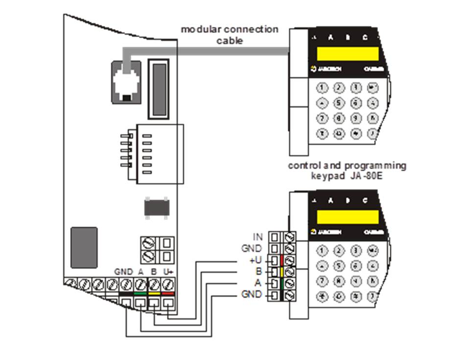
The central unit can be operated and programmed by JA-81F wireless keypads AND/OF by JA-81E hard-wired keypads. A hard-wired keypad can be connected to the control panel by a telephone cable with RJ connectors on the digital bus input, or by twisted pair cable of up to 100 metres wired via the connectors provided see diagram above. ( GND, A, B, +U)
We recommend including only 1 wired keypad in a system.
6 Backup battery
The unit can be equipped with a Jablotron backup battery of 1.3 or 2.2 Ah, depending on the demand for autonomy.
Euro-standard EN 50131-1 requires 12 h minimum backup time for grade 2 systems.
Wireless items are not powered by the control centre.
With a 1.3 Ah backup battery, 12h backup time can be achieved if the power consumption does not exceed 85mA. With the 2.6 Ah battery, you have double the capacity (170mA). This calculated at 80% of the battery capacity as 20% is provided for aging battery effect.
- The average life of the backup battery is up to 5 years, after which it must be replaced. The battery in the system will be charged automatically, and the status will be displayed by the system. When the system is running on battery power only, a technical alarm will occur when the backup battery is low.
Make sure the battery is connected correctly ( Polarity: Red = Positive +, Black = Negative - )
Warning: The battery is already charged when purchased - for safety's sake, avoid short-circuiting the outputs.
7 Putting the central unit into operation
- Check the wiring, when the GSM communicator is installed, insert the SIM card. (remove pin code)
- Carefully connect the backup battery
- Carefully connect the power. A green LED will start flashing on the control panel PCB.
- If a hard-wired keypad is installed it will be in service mode. If not in service mode the central controller is not in factory default, in this case a reset is required (see chapter 9)
7.1 Reading in the wireless keypad
When no hard-wired keypad is connected to the central controller, and the wireless keypad was not in the kit, the wireless keypad must be read into the central controller as follows:
1. Have an opened keypad and the batteries ready.
2. Check that the green LED of the central controller is flashing.
3. Short-circuit the reset link using a jumper for about 1 second, this puts the central unit into read-in mode.
4. Insert batteries in the keypad near the central unit.
5. The keypad will give a beep and will be read in to the first free zone. You will now see the following on the keypad: "Enrollment 04:Device".
6. Press # to exit the read-in menu to enter "Service" mode
Warning:
-When the keypad has not been read in, the settings are not the factory settings. In this case, do a full reset and repeat previous steps.
- If you want to read in a keypad to another zone, go back to read-in mode via the "1"key, select the correct address via the arrow keys, remove the battery and then replace the battery in the keypad.
Recommendation:It is highly recommended to install the keypad with a magnetic contact wired to the input of the keypad. This way, the keypad will come out of sleep mode every time the door is opened. Then you will also hear the input delay beeps on the keypad, and the card can then be read immediately.
8 Language selection of the keypad
If the * key is pressed continuously during the battery connection, the internal menu will allow the selection of the language.
Select the correct language using the arrow keys and confirm with the * key.
This menu can also enable or disable the doorbell function of the keypad.
Notes:
- If the batteries were already connected in the wireless keypad, the batteries must first be removed for a short time before pressing the * key.
- A different language can be selected for each keypad in 1 system, useful for places with people of different nationalities.
9 Resetting the control panel
When you want to return to factory settings, do the following:
1. Remove the backup battery and disconnect the power (e.g. by removing the fuse).
2. Short-circuit the reset link via a jumper contact
3. Reconnect the backup battery and power.
4. Wait until the green LED starts flashing, then remove the jumper from the reset link.
Warning:
-After a reset, all wireless items are removed from the system, and all user names and user codes are erased.
- After a reset, the master code will be 1234 again, and the service code 8080, resetting can be deactivated -> see chapter 12.9
10 Closing the cover of the control unit
.After the keypad is operating, you can close the cover of the central controller. Before closing the lid, check the connection of the antenna in the central unit.
11 Reading in wireless items
The control unit has 50 zones (01 to 50), 50 wireless items can be read in, e.g. detectors, keypads, remote controls, sirens,... The wireless items can be read in on some specific zones by reading them in or via the production code -> see chapter 12.41
11.1 Installing wireless items
Wireless items can be installed first, and then read into the system, or visa versa. If you are unsure about the range of the radio signal, you can test this communication first (code 298) before proceeding with installation. Follow the instructions for the individual items during installation.
11.2 Reading wireless items into the central unit
1. If you are not in "Service" mode, press *0 service code, factory setting is *08080. The PBX must not be armed.
2. Press the "1"key, now you enter read-in mode, the first free address appears on the screen. For a new PBX, this address is 04
3. Use the arrow keys if you want to select another zone. If the zone is already occupied, the A LED will light up red.
4. The item will be read in as soon as the battery is connected, in doing so the A led will light red on which will then display the next free zone.
5. By connecting all batteries in the various items, they will all be read in to the control panel. Press the # key to exit read-in mode to return to service mode.
Notes:
-When a wireless element is read into zone 1 or 2, the corresponding hard-wired input will be closed, on clearing the wireless zone it will become active again.
- Remote control type RC-8x can be read in by holding down both keys, e.g:![]() +
+ ![]() or
or![]() +
+ ![]()
- So for a remote control with 4 buttons, 2 separate zones will be read in.
- Only 1 element can be read into a zone.
- When LED A lights up, it means that the indicated zone is already occupied and therefore no items can be read into this zone.
- When an item has already been read into a certain zone, and you read this item into another zone afterwards, the item will have the address of the new zone, the previous zone will be free again for new items.
- If an item cannot be read into the central controller, then either the wireless connection is insufficient due to long distance, or the distance between item and central controller is too small ( one should keep at least 2 metres distance).
- To read in an item, first remove the battery from the item, wait about 10 seconds before reinserting the batteries. By pressing the tamper, the remaining battery voltage will discharge more quickly, and you do not have to wait.
- A sub PBX can be read in to the "Master" PBX by keying 299 on the keypad of the sub PBX in service mode.( See chapter 12.10)
- If you want to apply final door detectors in a system, they must be read in at address 00 to 05 or 46 to 50 ( See chapter 12.23)
11.3 Testing read-in items
1. The antenna of the central unit should be connected, if not in service mode, press *0 8080 to enter service mode. Service mode only possible if the system is not armed.
2. Trigger the item to be tested ( for a detector, open and close the cover and wait until it is ready to be tested)
3. The keypad will beep and will display the signal strength of the item under test ( the cover of the keypad is best open). We recommend taking the keypad to the location of the items to be tested.
Note:
-Motion detectors JA-80P and JA-85P can be tested up to max 15 minutes after closing the cover. After this period, the detector will ignore the changes (see detector manual for details)
- Items can also be tested in maintenance mode.
11.4 Measuring signal strength
The antenna of the control unit should be connected,if not in service mode, press *0 8080 to enter service mode. Service mode only possible if the system is not armed.
1. Press 298, the lowest read item will be displayed.
2. Trigger the item of the displayed zone. The keypad will now display the signal strength of the triggered zone on a scale of ¼ to 4/4. Keep the keypad cover open while measuring the signals.
3. Other items can be selected via arrow keys for signal strength measurement.
4. With exit via # keys
Notes:
-Motion detectors JA-80P and JA-85P can be tested up to max 15 minutes after closing the cover. After this period, the detector will ignore the changes (see detector manual for details)
- Measuring the signal strength of the JA-80L indoor siren can be triggered by pressing the siren button. The signal strength of the outdoor JA-80A siren can be measured by opening the cover wading through the tamper triggered.
- Each installed item should have a minimum signal strength of at least 2/4. If the signal is too weak, the sensitivity of the station can be increased (see 12.35). Furthermore, an external antenna can also be installed to increase the range.
- The measured signal strength is the signal of the tested item and the PBX receiving the signal.
11.5 Deleting read items
If not in service mode, press *0 8080 to enter service mode. Service mode only possible if the system is not armed.
1. Press "1"to enter read-in mode, and use the arrow keys to go to the zone you wish to delete.
2. Press and hold the "2"key until you hear a beep and the A LED no longer lights up. -> zone cleared
Press # to exit the menu
Note:
-To clear all zones in read-in mode, hold down the "4" key.
- When a wireless keypad is cleared, communication between keypad and central station will be gone. The keypad must then be read back in (see chapter 7.1)
11.6 Reading in the central unit into the UC and AC modules:
If you wish to use the PGX and PGY outputs of the central controller via the UC and AC modules, they must be read in as follows:
1. The central controller must be in service mode, if not, press *0 service code ( factory setting : 8080)
2. Set the UC or AC module to the desired read-in mode ( see UC/AC module manual)
3. Press "299"on the keypad of the central controller and check that all LEDs on the read module light up several times to confirm the read-in.
Notes:
-As the read-in times of the UC and AC modules are very short, we recommend keeping the modules near the central controller during the read-in process. Alternatively, keep the keypad close to the item to be read during the read-in.
- The central unit can be read in to several UC/AC modules for multiple PG outputs in an installation.
- Each UC/AC module has 2 relays,X and Y that need to be read in separately. The X output will respond to the PGX output of the central controller and the Y to the Y output of the central controller
- Only 1 central controller can be read in to a UC/AC receiver because the central controller repeats its PG signals every 9 minutes.
12 Programming the central controller
The most user-friendly way to programme the system is via the included PC Comlink Software. The system can also be programmed via code structure see table of chapter 12.1
- The system must be in service mode, if not, press *0 service code ( factory setting service code = 8080)
- Press the desired code see table 12.1
- Leave the menu via # key